
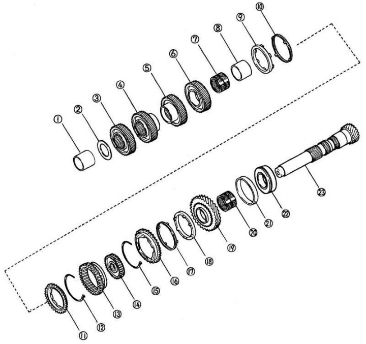
Fig. 3.36. Output shaft: 1 – spacer sleeve; 2 – retaining ring; 3 – intermediate gear of the fifth gear; 4 – fourth gear intermediate gear; 5 – intermediate gear of the third gear; 6 – intermediate gear of the second gear; 7 – needle bearing; 8 – spacer sleeve; 9 – inner synchronizer ring; 10 – outer synchronizer ring; 11 – synchronizer ring; 12 – synchronizer spring; 13 – intermediate gear; 14 – synchronizer clutch; 15 – synchronizer spring; 16 – synchronizer ring; 17 – outer synchronizer ring; 18 – inner synchronizer ring; 19 – intermediate gear of the first gear; 20 – needle bearing; 21 – outer bearing ring; 22 – tapered bearing; 23 – output shaft
Examination
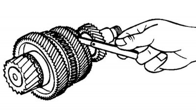
Fig. 3.37. Measuring the clearance between the output shaft and the bearing
Measure the clearance between the output shaft and the bearing (Fig. 3.37).
If the clearance is greater than the maximum allowable, check the contact surfaces of the third gear intermediate gear, the first gear intermediate gear of the output shaft and the synchronizer clutch (1st gear - 2nd gear) as an assembly. Replace damaged parts.
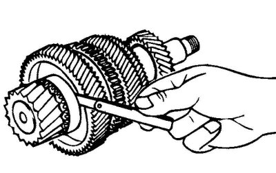
Fig. 3.38. Measuring the gap between the second gear intermediate gear and the third gear intermediate gear
Measure the clearance between the second gear intermediate gear and the third gear intermediate gear (Fig. 3.38).
If the clearance is greater than the maximum allowable, check the contact surfaces of the second gear intermediate gear, third gear intermediate gear and synchronizer clutch (1st gear – 2nd gear) as an assembly. Replace damaged parts.
Disassembly
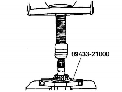
Fig. 3.39. Removing 5th gear components
Remove the bearing and 5th gear idler using SST (Fig. 3.39).
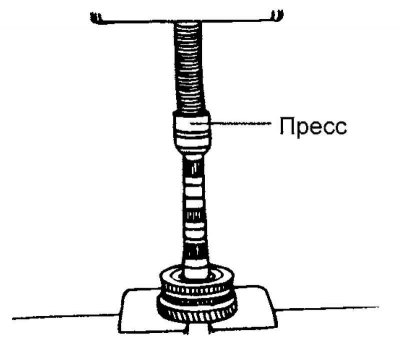
Fig. 3.40. Removing the synchronizer clutch
Remove the synchronizer sleeve (1st gear – 2nd gear) as an assembly, the first gear synchronizer ring and the first gear intermediate gear using a press (Fig. 3.40).
Assembly
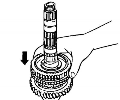
Fig. 3.41. Assembly of 1st and 2nd gear components
Assemble the first gear intermediate gear, first gear synchronizer ring and synchronizer sleeve (1st gear – 2nd gear) as an assembly, as shown in the figure (Fig. 3.41).
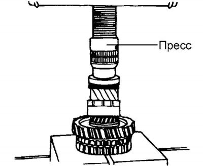
Fig. 3.42. Pressing in the synchronizer clutch
Press in the synchronizer sleeve (1st gear – 2nd gear) as an assembly (Fig. 3.42).
Measure the clearance between the first gear intermediate gear and the differential drive gear.
Measure the clearance between the second gear idler gear and the third gear idler gear.