
Contents: Disassembly ⇓ Assembly ⇓
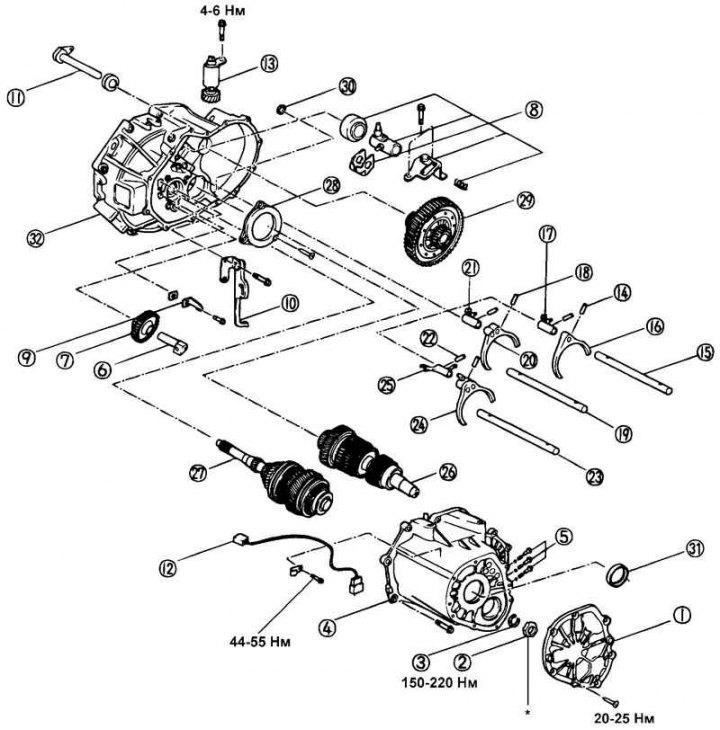
Fig. 3.8. Components of a manual transmission: 1 – back cover; 2 – lock nut; 3 – retaining ring; 4 – gearbox housing; 5 – retainer plug, spring and ball; 6 – reverse intermediate gear shaft; 7 – intermediate reverse gear; 8 – reverse gear engagement fork assembly; 9 – reverse gear engagement linkage (spring); 10 – reverse gear engagement lever; 11 – Reverse gear engagement limiter; 12 – Reversing light switch; 13 – driven gear of the speedometer drive; 14 – locking pin; 15 – 1–2 gear shift fork rod; 16 – 1–2 gear shift fork; 17 – 1-2 gear shift fork rod tip (1-2 gear shift head); 18 – locking pin; 19 – 3-4 gear shift fork rod; 20 – 3-4 gear shift fork; 21 – 3-4 gear shift fork rod tip (3-4 gear shift head); 22 – locking pin; 23 – 5th gear shift fork rod; 24 – 5th reverse gear shift fork; 25 – 5-reverse gear shift fork rod tip (5-reverse gear shift head); 26 – input shaft; 27 – output shaft; 28 – bearing cap; 29 – differential assembly; 30 – magnet; 31 – oil seal; 32 – clutch housing
Disassembly
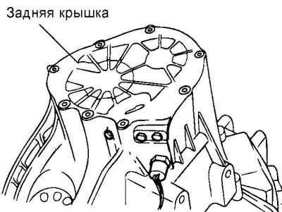
Fig. 3.9. Back cover
Remove the rear cover of the gearbox housing, the lock nut and the retaining ring (Fig. 3.9).
Remove the retainer plug, spring and ball.
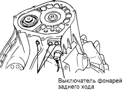
Fig. 3.10. Reverse light switch
Remove the reversing light switch (Fig. 3.10).
Remove the bolts holding the rear housing and main housing together.
Remove the reverse idler gear shaft and reverse idler gear.
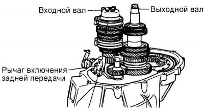
Fig. 3.11. Removing the reverse gear engagement limiter
Remove the reverse gear engagement linkage (spring) (Fig. 3.11).
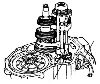
Fig. 3.12. Reverse gear engagement fork assembly
Remove the reverse gear engagement limiter and the reverse gear engagement fork assembly (Fig. 3.12).
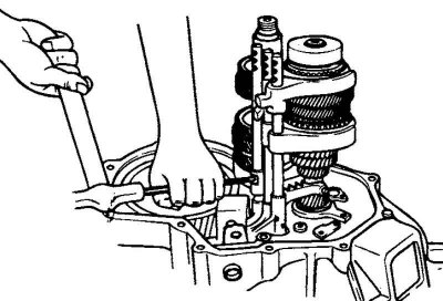
Fig. 3.13. Removing the locking pin from the fork and the rod end assembly with pin stamping
Carefully remove the locking pin from the fork and rod end assembly with the pin stamping (Fig. 3.13).
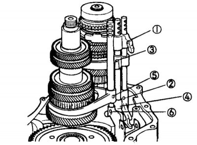
Fig. 3.14. Procedure for removing locking pins
Remove all locking pins, the location of which is shown in the figure (Fig. 3.14).
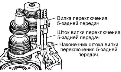
Fig. 3.15. 5-reverse shift fork rod, 5-reverse shift fork and 5-reverse shift fork rod tip
Remove the 5-reverse shift fork rod, 5-reverse shift fork and 5-reverse shift fork rod end (Fig. 3.15).
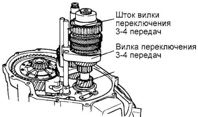
Fig. 3.16. Fork stem and 3-4 gear shift fork
Remove the 3-4 shift fork shaft, 3-4 shift fork and 3-4 shift fork shaft tip (3-4 shift head) (Fig. 3.16).
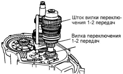
Fig. 3.17. Fork stem and 1–2 gear shift fork
Remove the 1-2 shift fork rod, 1-2 shift fork and 1-2 shift fork rod end (1-2 shift head) (Fig. 3.17).
Remove the input and output shaft synchronizer gears and sleeves in the sequence shown, and then remove the main shaft (Remove the input and output shaft synchronizer gears and sleeves).
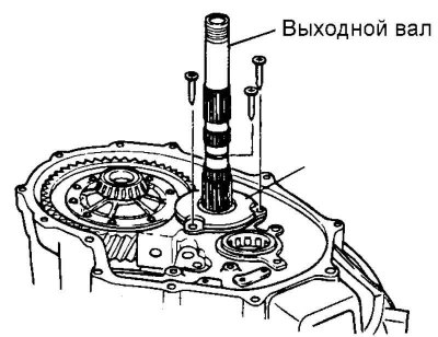
Fig. 3.18. Output shaft
Remove the rings, bearings and synchronizer sleeve assembly from the input shaft. Remove the four bearings and remove the output shaft (Fig. 3.18).
Remove the differential assembly.
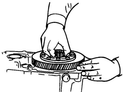
Fig. 3.19. Removing the differential
Remove the speedometer drive driven gear after removing the bolt (Fig. 3.19).
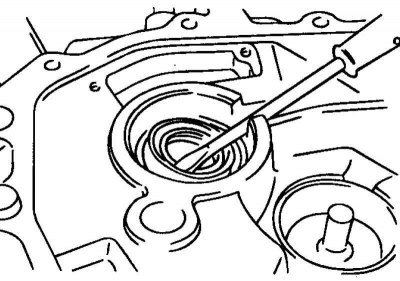
Fig. 3.20. Removing the input shaft seal
Remove the input shaft seal using a screwdriver or suitable tool (Fig. 3.20).
Remove the oil seal cover.
Remove the reverse gear limiter seal using a screwdriver or suitable tool.
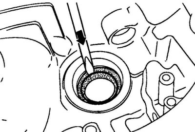
Fig. 3.21. Removing the input shaft seal
Remove the differential seal using a screwdriver or suitable tool (Fig. 3.21).
Assembly
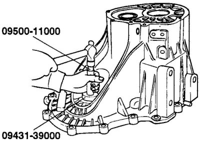
Fig. 3.22. Installing the drive shaft seal
Install the drive shaft seal (Fig. 3.22).
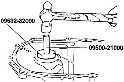
Fig. 3.23. Installing gearbox bearings
To assemble the gearbox bearings and install the differential housing, use a special tool (Fig. 3.23).
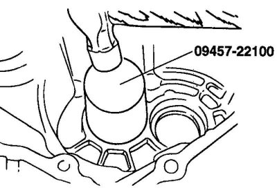
Fig. 3.24. Installing the differential seal
Install the differential seal (Fig. 3.24).
Install the speedometer drive driven gear.
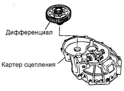
Fig. 3.25. Installing the differential
Install the differential into the clutch crater (Fig. 3.25).
Install the input and output shafts into the clutch cavity.
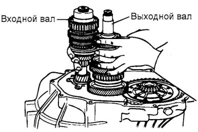
Fig. 3.26. Installing the input and output shaft gears
Install the synchronizer gears and clutches as an assembly on the input and output shafts (Fig. 3.26).
Install the 1-2 shift fork shaft, 1-2 shift fork and 1-2 shift fork shaft tip (1-2 shift head).
Install the 3-4 shift fork shaft, 3-4 shift fork and 3-4 shift fork shaft tip (3-4 shift head).
Install the 5-reverse shift fork shaft, 5-reverse shift fork and 5-reverse shift fork shaft tip.
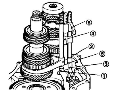
Fig. 3.27. The order of installation of locking pins
Install the fork and fork rod locking pins as an assembly in the order shown in the figure (Fig. 3.27).
Install the reverse gear fork assembly and reverse gear limiter and tighten with the two reverse gear fork bolts.
Install the reverse gear lever and tighten the two reverse gear lever bolts.
Install the reverse gear engagement linkage (spring).
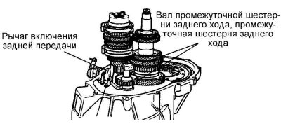
Fig. 3.28. Reverse intermediate gear shaft and reverse intermediate gear
Install the reverse intermediate gear shaft and the reverse intermediate gear (Fig. 3.28).
Attach the magnet to the clutch crater.
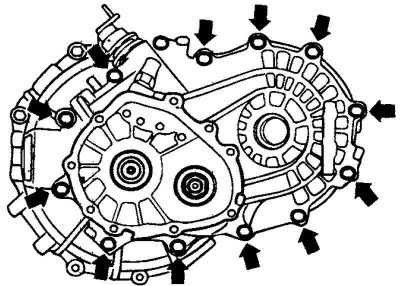
Fig. 3.29. Gearbox mounting bolts
Secure the gearbox with the mounting bolts (Fig. 3.29).
Install the reversing light switch.
Install plugs, seats, springs and balls.
Install the output shaft lock nut.
Install the back cover.