
Contents: Removal ⇓ Assembling the crankcase and…⇓ Removal the inner drive shaft ⇓ Installing the bearing and retaining…⇓ Assembly of hollow shafts ⇓
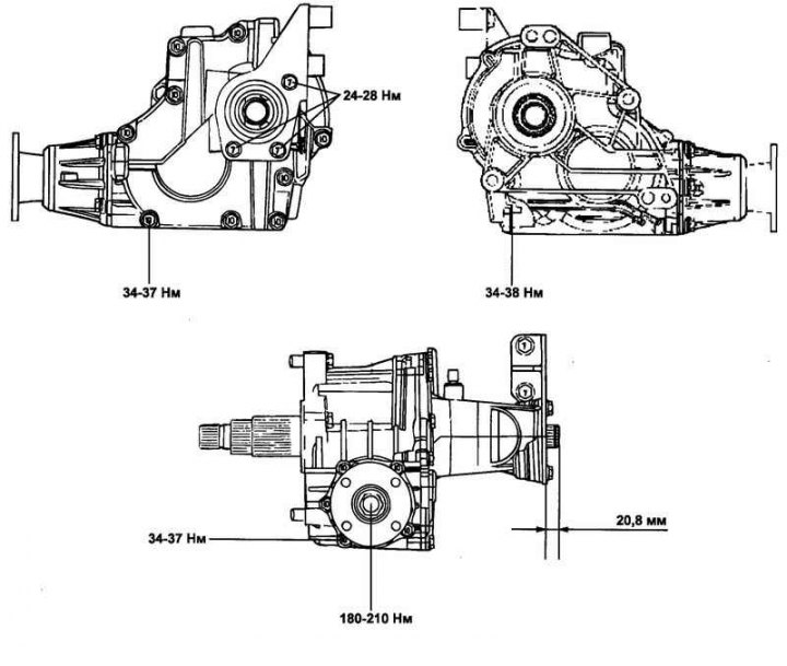
Fig. 3.48. External view of the transfer case
Removal
Secure the engine to the special fixture (crossbar 09200-38001) using the mounting brackets (if necessary).
Remove the transfer case and subframe.
Raise the car and remove the wheels.
Remove the front muffler.
Drain the oil from the transfer case housing.
Remove the lower engine cover and side cover.
Remove the brake caliper, shock absorbers and drive shafts.
Remove the generator, exhaust manifold and fan shaft.
Remove the steering column secured to the subframe.
Remove the subframe mounting bolts and remove the subframe assembly.
Remove the transfer case mounting bolts.
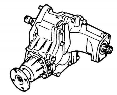
Fig. 3.49. Transfer case assembly
Remove the transfer case assembly (Fig. 3.49).
Assembling the crankcase and transfer case cover
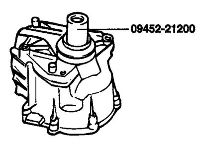
Fig. 3.50. Installing the oil seal on the transfer case housing
The installation of the oil seal on the transfer case housing is carried out using a special tool (Fig. 3.50).
Removal the inner drive shaft
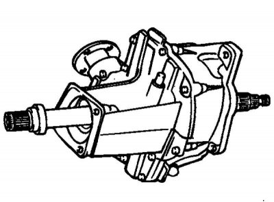
Fig. 3.51. Drive shaft seal
Remove the oil seal (Fig. 3.51).
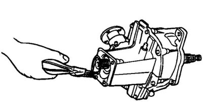
Fig. 3.52. Removing the retaining ring
The article is borrowed from the website hyundaibook.ru
Remove the retaining ring (Fig. 3.52).
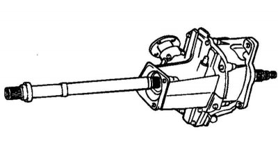
Fig. 3.53. Removing the inner drive shaft
Remove the inner drive shaft (Fig. 3.53).
Removing the inner drive shaft bearing
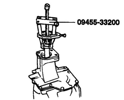
Fig. 3.54. Removing the inner drive shaft bearing
Remove the inner drive shaft bearing using a special tool (Fig. 3.54).
Installing the bearing and retaining ring
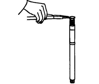
Fig. 3.55. Installing the retaining ring
Install the retaining ring on the inner drive shaft (Fig. 3.55).
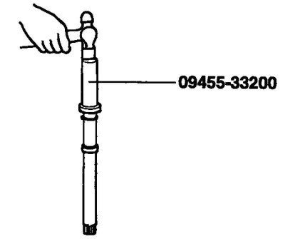
Fig. 3.56. Installing a ball bearing
Install the ball bearing and ring (Fig. 3.56).
Assembly of hollow shafts
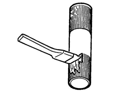
Fig. 3.57. Applying lubricant
Apply grease to the surface of the hollow shaft (Fig. 3.57).
LUBRICANT: CLUBER MICROLUBE GNY202 or equivalent.
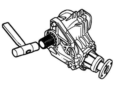
Fig. 3.58. Installation of the outer hollow shaft
Install the outer hollow shaft (Fig. 3.58).
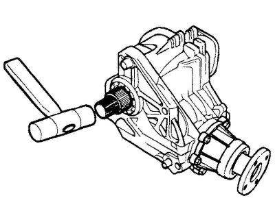
Fig. 3.59. Installing the inner hollow shaft
Install the inner hollow shaft (Fig. 3.59).