
Contents: System components and their operation ⇓ Removal ⇓ Checking the main switch of the SPPS ⇓ Checking the brake light switch ⇓ Checking the work ⇓ Troubleshooting Guide ⇓ Adjusting the cable ⇓
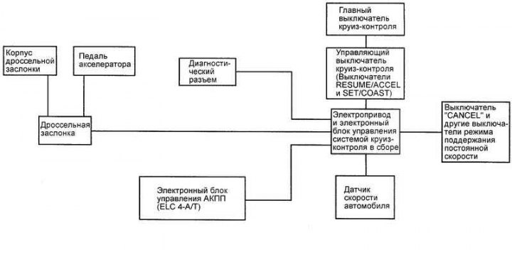
Fig. 7.71. Block diagram of the constant speed maintenance system
System components and their operation
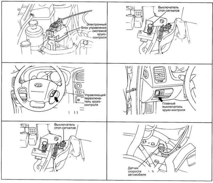
Fig. 7.72. Location of cruise control system components
The arrangement of the components of the cruise control system is shown in Fig. 7.72 and 7.73.
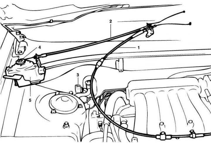
Fig. 7.73. Connecting the cables and electrical connectors of the constant speed control system: 1 – connection of the accelerator pedal cable and the connector housing assembly; 2 – connection of the cruise control drive cable and the connector of the electric drive sector of the cruise control system; 3 – Cruise control system electric drive connector; 4 – sector of the electric drive of the cruise control system; 5 – Electric drive of the cruise control system
Removal
Disconnect the battery.
Disconnect the accelerator and ESP control cables from the throttle body.
Disconnect the accelerator cable from the accelerator pedal.
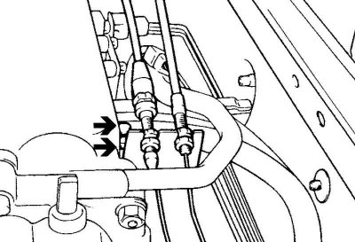
Fig. 7.74. Accelerator cable support clips
Loosen the bolts securing the accelerator cable support clips (Fig. 7.74).
Loosen the bolts securing the SPS drive and remove the drive.
Installation is carried out in reverse order.
Checking the main switch of the SPPS
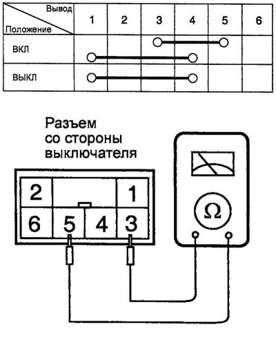
Fig. 7.75. Circuit diagram for testing the main switch of the SPPS
Check the switch circuits according to the table in Figure 7.75.
If the test results are negative, replace the switch.
Checking the brake light switch
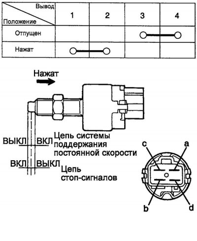
Fig. 7.76. Brake light switch test diagram
Check the switch circuits with the switch button pressed and released (Fig. 7.76).
Checking the work
Checking and adjusting the system operation is carried out with the electrical loads turned off.
Warm up the engine until the idle speed stabilizes. Check that the speed complies with technical standards.
Turn off the ignition.
Make sure there are no sharp bends in the control cables.
Press the accelerator pedal: the throttle lever should move from stop to stop smoothly, without jerking.
Check the cable tension adjustment.
If there is excessive slack or no slack at all, adjust the tension of the cables.
Troubleshooting Guide
If the cables are too loose when moving uphill, there will be a significant drop in speed
If there is no slack in the cable, the idle speed will be higher than normal.
Adjusting the cable
Connect the cable to the drive traction roller.
Pull the cable sheath until the slack in the cable is taken up. Tighten the nut "b" until it touches the bracket.
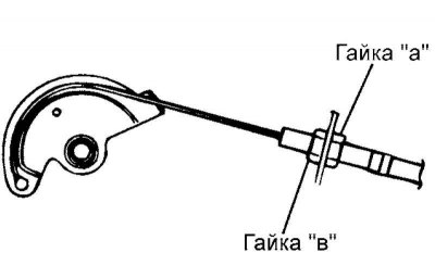
Fig. 7.77. Accelerator cable adjustment diagram
Loosen nut "b" one turn (Fig. 7.77).
Tighten lock nut "a".
As a result of the actions taken, the deflection of the cable between the roller and the bracket should be approximately 1 mm (the drive roller comes to rest).