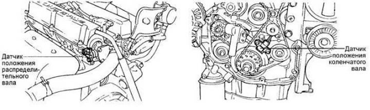
Fig. 7.2. Ignition control system components
Measuring the resistance of the primary winding of the ignition coil
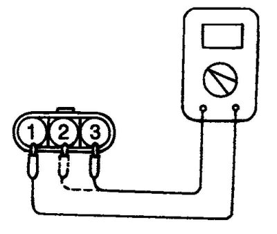
Fig. 7.3. Measuring the resistance of the primary winding of the ignition coil
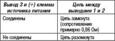
Connect the wire from the negative (–) terminal of the 3 V power source to terminal 2 of the ignition coil. Then check the condition of the circuit with terminals 1 and 2 of the ignition coil with the positive (+) terminal of the power source disconnected and connected from terminal 3 of the ignition coil (Fig. 7.3).
Measuring the resistance of the secondary winding of the ignition coil
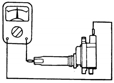
Fig. 7.4. Measuring the resistance of the secondary winding of the ignition coil
Measure the resistance between the high voltage terminal and the spark plug wire terminal of the ignition coil (Fig. 7.4).
Nominal value: approximately 12.1 kOhm.