
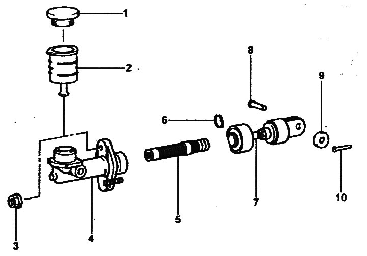
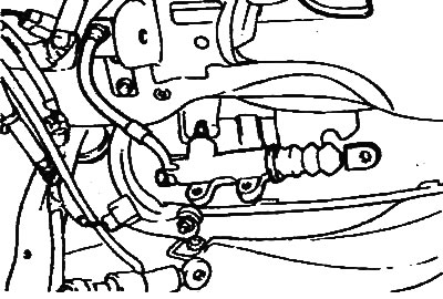
Clutch release master cylinder.
1 - tank cover, 2 - working fluid tank, 3 - nut, 4 - cylinder body, 5 - piston, 6 - retaining ring, 7 - rod assembly with fork, 8 - pin, 9 - washer, 10 - cotter pin.
Removal
1. Drain the clutch fluid through the bleed nipple.
2. Remove the cotter pin, stud and washer.
3. Disconnect the hydraulic hose from the clutch release master cylinder.
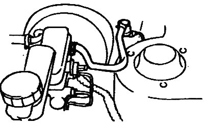
4. Loosen the master cylinder mounting bolt.
- Tightening torque: 8-12 Nm
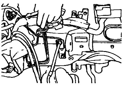
5. Remove the clutch hydraulic tube clamps.
6. Having secured the clutch hydraulic hose nut, unscrew the tube mounting nut.
- Tightening torque: 12-16 Nm
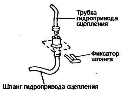
7. Remove the retainer from the clutch hydraulic hose, then disconnect the hose from the bracket.
8. Remove the clutch hydraulic tube.
9. Disconnect the clutch hydraulic drive slave cylinder pipe.
Disassembly
1. Remove the piston retaining ring.
2. Remove the rod and piston assembly.
Note:
- Be careful not to damage the piston assembly and the master cylinder body.
- Do not disassemble the clutch master cylinder piston.
3. If necessary, remove the reservoir cap, reservoir mounting clamp and clutch reservoir.
Examination
1. Check the inner surface of the master cylinder body for rust, corrosion (pitting) and scoring.
2. Check the piston cover for wear and deformation.
3. Check the piston for rust, corrosion (pitting) and scoring.
4. Check the clutch hydraulic tubes for blockages.
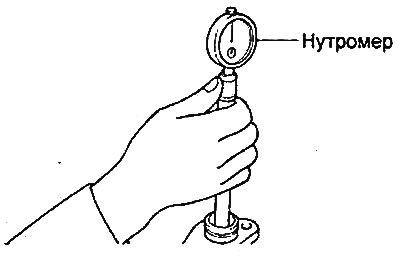
5. Measure the inside diameter of the master cylinder with a bore gauge and the outside diameter of the piston with a micrometer.
Note: After installing the bore gauge in the master cylinder, measure the diameter in three sections by moving the bore gauge in the axial direction. Then turn the bore gauge 90° and repeat the operation. All six values obtained must satisfy the technical data.
- Nominal value: 15.87 mm
6. Measure the outside diameter of the piston with a micrometer and calculate the clearance between the piston and the master cylinder body (the difference between the inside diameter of the master cylinder and the outside diameter of the piston).
If the clearance exceeds the maximum permissible value, replace the master cylinder and/or piston assembly.
- Maximum permissible value: 0.15 mm
7. Check the clutch hydraulic hose or tube for cracks, damage or clogging.
Assembly
1. Assembly is carried out in the reverse order of disassembly.
2. When assembling, apply working fluid to the inner surface of the clutch release master cylinder housing and to the outer surface of the piston.
- Working fluid type: brake fluid SAE J 1703 (DOT3)
Installation
1. Installation is carried out in the reverse order of removal; the tightening torques of the bolts and nuts are indicated in the text describing the removal procedure.
2. When connecting the piston rod fork to the clutch pedal, apply grease to the pin and washer at the clutch pedal joint.
- Lubrication: SAE J310, NLGI No.2 hub bearing grease
3. After installation, bleed the clutch release drive.