
Contents: Installing the locking cam ⇓ Adjusting the selector lever lock…⇓ Checking the correct installation of…⇓
Note: To ensure normal operation of the Hyundai Getz selector lever lock mechanism, install in the following sequence.
Installing the locking cam
1. Move the locking cam "P" in the direction of arrow "A" and hold it with your hand.
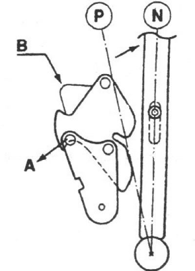
2. Make sure the locking cam is held in position "B" by the locking pin.
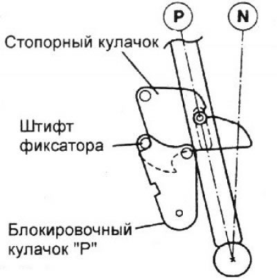
Adjusting the selector lever lock cable and stopper cable
1. Make sure each of the locking cams is in the position shown in the illustration.
2. Install the selector lever lock cable and the stopper cable, securing the stopper cable to the stopper cylinder and the lock cable to the brake pedal.
3. Temporarily attach both cables to the gearshift lever as shown. Securely connect the cables to the mounting pin of each cam.
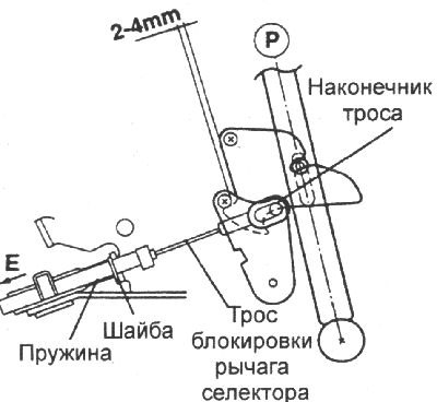
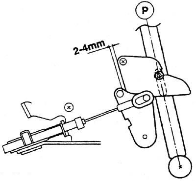
4. Remove the slack in the selector lever lock cable by pulling it slightly, leaving a gap of 2–4 mm between the locking cam and the "P" locking cam.
5. Make sure that the end of the cable contacts the pin securing the cable to the locking cam "P", secure the locking cable to the gearshift lever with the nut and the end of the locking cable with the washer and pin.
Checking the correct installation of the selector lever locking mechanism
1. If the brake pedal is not pressed, the selector lever handle button in the "P" position does not work, and the selector lever cannot be moved from the "P" position. In other selector lever positions, the button works.
2. When the brake pedal is pressed 15–25 mm in the "P" position of the selector lever, the button can move freely and the selector lever can move smoothly from the "P" position.
3. If the brake pedal is not pressed, the selector lever can smoothly move to the "P" position from other positions.
4. The brake pedal can be pressed smoothly and freely in any position.
5. In the "LOCK" position of the key in the ignition switch, the button should not work even when you press the brake pedal.
The original can be found on the resource: hyundaibook
6. Before and after adjustment, the locking cam and the blocking cam "P" must not be in the position shown in the figures
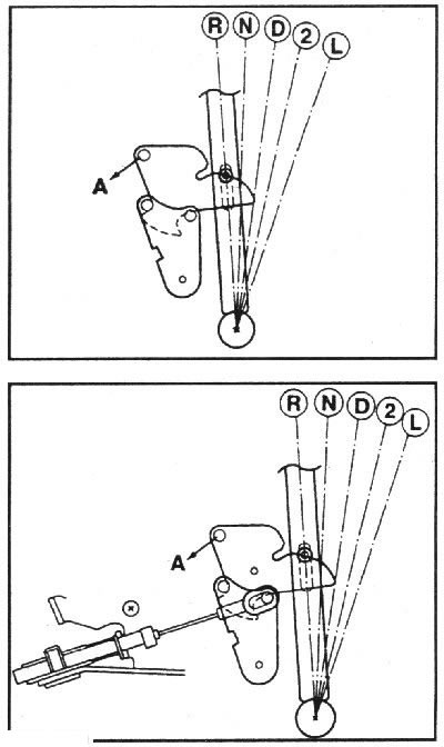
Note: If the locking stop cam and the P-shaped locking cam are in the positions shown in the penultimate figure, moving the selector lever from the "D", "3", "2", "L" positions to the "P", "R", "N" positions with great force may cause damage to the interacting elements. If the cams are in the position shown in the penultimate figure, move the selector lever from the "D", "3", "2", "L" positions to the "P", "R", "N" positions after turning the P-shaped locking cam in the direction of arrow "A". If the cams are in the position shown in the last figure, move the selector lever from the "D", "3", "2", "L" positions to the "P", "R", "N" positions after turning the P-shaped locking cam in the direction of arrow "A" while depressing the brake pedal.