
Contents: Headlight adjustment ⇓ Adjusting fog lights ⇓ Replacing lamps ⇓ Removal and installation headlights ⇓ Removal and installation fog lights ⇓ Removal and installation the turn…⇓ Removal and installation of tailgate…⇓ Removal and installation additional…⇓ Removal and installation the…⇓ Steering column switch block ⇓
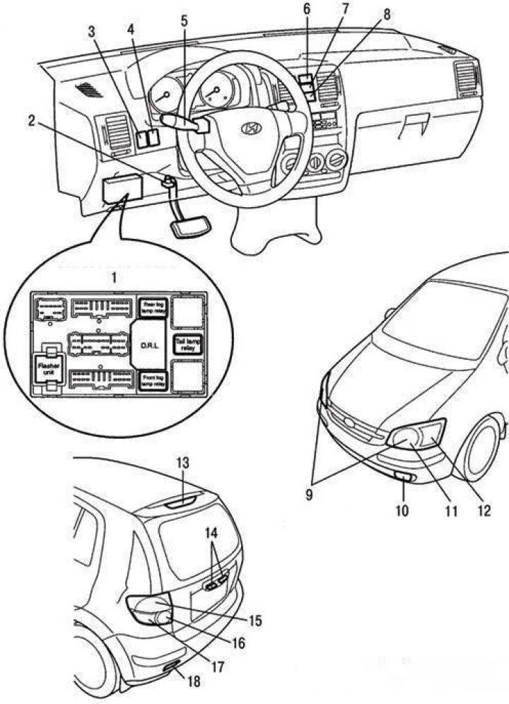
Instruments and controls of the vehicle's lighting and light signaling system: 1 – fuse and relay box in the car interior; 2 – brake light switch; 3 – Instrument cluster lighting brightness control; 4 – headlight corrector switch; 5 – External lighting switch; 6 – hazard warning switch; 7 – fog light switch; 8 – Rear fog light switch; 9 – headlight bulbs; 10 – fog light; 11 – side light bulb; 12 – direction indicator lamp; 13 – additional brake signal; 14 – License plate lights; 15 – parking light and brake light; 16 – Reverse light lamp; 17 – direction indicator lamp; 18 – rear fog light
The lighting system includes the main headlights (headlamps), taillights, brake lights, reversing lights, turn signals, fog lights and rear fog lights, license plate lights, engine compartment lights and interior lights. Before replacing the bulbs, check the corresponding fuse and disconnect the corresponding consumer. The instruments and controls of the vehicle's lighting and light signaling system are shown in the figure.
| Color of carbon deposits | Possible reason |
| Dark colored carbon deposits | Over-enriched air-fuel mixture Insufficient air content in the mixture |
| Light colored carbon deposits | Lean air-fuel mixture Too early ignition Loosening spark plugs |
Headlight adjustment
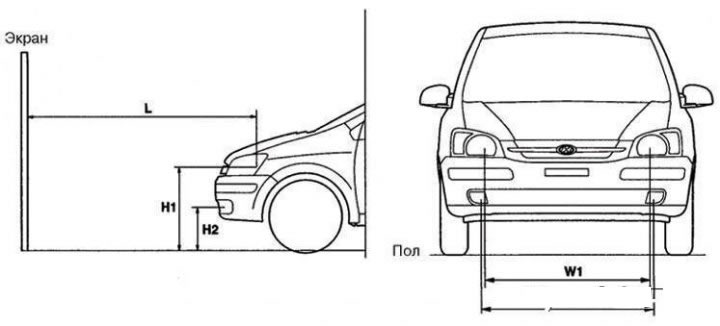
Headlight adjustment diagram: H1 – height of the headlamp bulb center above the ground; H2 – height of the center of the fog lamp above the ground; W1 – distance between the centers of the headlight bulbs; W2 – distance between the centers of the fog lamps; L – distance between headlight bulb and screen
Adjust the direction of the headlight beams using a device in accordance with the manufacturer's instructions.
Note: Adjust the headlights in accordance with the laws in force in the region where the vehicle is operated.
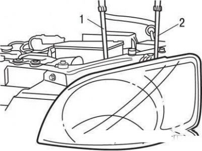
Headlight adjustment: 1 – adjustment of the light beam in the horizontal direction; 2 – adjustment of the light beam in the vertical direction
The headlights are adjusted by turning the adjusting screws. If there is no special equipment, the adjustment can be done as follows.
Set the required tire pressure. There should be no load in the car except for the driver, spare tire and on-board tool. The battery and headlights should be in good condition.
Place the vehicle on a level, horizontal surface.
On the screen for adjustment, draw two vertical and one horizontal lines. The intersection points of the lines determine the position of the centers of the headlight beams.
Use the adjustment screws to move the brightest areas of the light beams to the intersection points of the lines on the screen.
Make adjustments with the low beam headlights on.
Adjusting fog lights
Adjust the fog lights as specified for the headlights, provided that the fog lights and battery are in good condition.
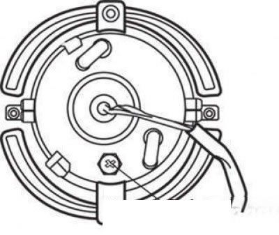
Fog light (rear view): 1 – adjusting screw
Adjust the direction of the fog light beams with the adjusting screw.
The adjustment diagram is shown in the figure.
Turn on the low beam headlights (car without a driver).
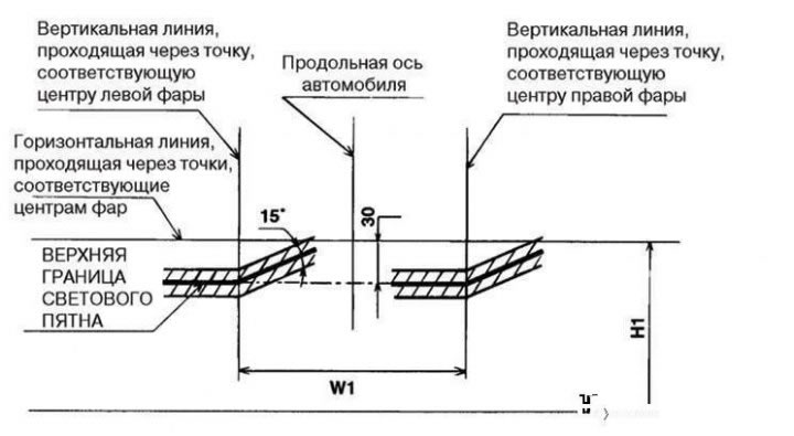
Headlight adjustment diagram
Adjust the position of the headlight beams so that the upper edges of the light spots are located within the shaded area of the screen.
Turn on the fog lights (car without driver).
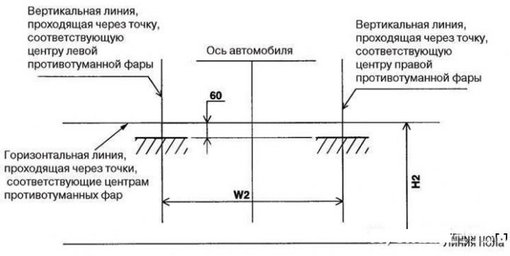
Fog light adjustment diagram
Adjust the position of the light spots so that their upper border is in the place shown in the figure (shaded areas).
Replacing lamps
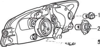
Headlamp bulbs: 1 – turn signal bulb; 2 – low/high beam lamp; 3 – side light lamp
To replace the low/high beam bulb, remove the cover from the back of the headlight. Disconnect the wires from the bulb, remove the spring clip tabs from the slots and remove the bulb.
Attention!
- Do not touch the bulb with bare hands. The oil from your fingers left on the bulb evaporates and may settle on the reflector, causing it to darken. Wipe off any stains that may have appeared from touching the bulb with a clean, lint-free cloth or remove them with alcohol.
- Be sure to replace burned-out bulbs with bulbs of the same type.
To replace the parking light bulb, remove the socket with the bulb from the optical element and remove the bulb from the socket.
To replace the turn signal bulb, remove the connector from the socket, turn the socket assembly counterclockwise and remove it from the socket.
Removal and installation headlights
Disconnect the cable from the negative ("–") terminal of the battery.
Remove the two bolts securing the upper trim of the front bumper.
Loosen the headlight mounting bolts and disconnect the contact connectors.
Installation is carried out in the reverse order of removal.
Removal and installation fog lights
Disconnect the cable from the negative ("–") terminal of the battery.
Remove the front fender liner.
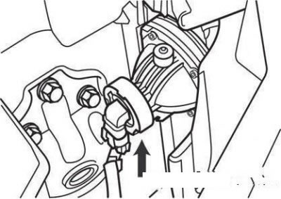
Fog lamp connector
Remove the fog lamp by unscrewing the mounting screws and disconnect the contact connector.
The headlight is installed in the reverse order of removal.
Removal and installation the turn signal lamp
Disconnect the cable from the negative battery terminal.
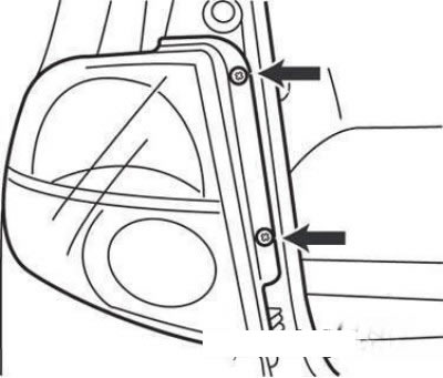
Tail light mounting screws
Remove the two screws securing the rear light.
Disconnect the rear light connector.
Installation is carried out in the reverse order of removal.
Removal and installation of tailgate mounted lights, parking light and license plate lights
Disconnect the cable from the negative ("–") terminal of the battery.
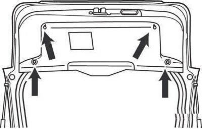
Tailgate trim mounting screws
Remove the rear door trim.
Remove the license plate light bulb and disconnect the connector.
Installation is carried out in the reverse order of removal.
Removal and installation additional brake light
Disconnect the cable from the negative ("–") terminal of the battery.
Remove the rear spoiler by unscrewing the four mounting nuts (on vehicles with a rear spoiler).
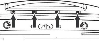
Additional brake light mounting screws
Loosen the four mounting screws, disconnect the connector and remove the additional brake light.
Installation is carried out in the reverse order of removal.
Removal and installation the interior light
Disconnect the cable from the negative ("–") terminal of the battery.
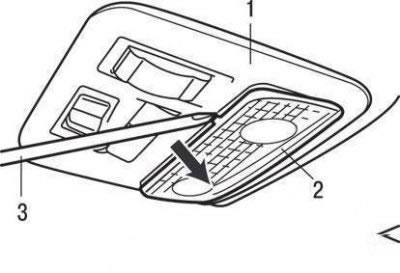
Removing the interior light: 1 – roof console; 2 – diffuser; 3 – screwdriver
Using a screwdriver, remove the diffuser from the roof console.
Loosen the mounting screws and disconnect the contact connector.
Installation is carried out in the reverse order of removal.
Steering column switch block
Safety precautions when removing the steering column switch assembly from vehicles equipped with airbags
When removing the steering column switch assembly on vehicles equipped with air bags, strictly follow these instructions.
Disassembling or repairing the airbag module and contact disk is prohibited. Replace them if faulty.
Do not allow the airbag module and contact disc to fall, or come into contact with water, grease, or oil. If there are dents, cracks, or deformations, replace the damaged parts.
Place the airbag module on a flat surface with the facing facing up. Do not place any objects on it.
Do not expose the air bag module to temperatures above 200°F (93°C).
After the airbag has deployed, replace the contact disc with a new one.
When handling a deployed airbag, wear protective gloves and goggles.
Dispose of the non-deployed airbag module in strict accordance with the instructions for passive safety systems.
When disconnecting the air bag module connector and the contact disc, do not apply excessive force.
Store the removed airbag module in a dry and clean place.
When installing the contact disc, align the installation mark with the neutral position index of the disc, set the steering wheel to the straight-ahead position, and connect the contact disc to the steering column switch. If the installation mark of the contact disc is not properly aligned with its neutral position index, the steering wheel will not turn a full angle when turning, or the flat wire inside the contact disc may break, which may cause the airbag to deploy abnormally and seriously injure the driver.
Removal and installation
Disconnect the cable from the negative ("–") terminal of the battery.
Remove the airbag module by removing the three mounting bolts and disconnecting the horn switch connector.
Caution: On vehicles without an airbag, remove only the horn switch cover.
Loosen the steering wheel mounting nut.
Remove the steering wheel using a puller.
Caution! When removing the steering wheel, do not hit it - this may damage the steering shaft folding mechanism.
Remove the steering column trim cover by unscrewing the three mounting screws.
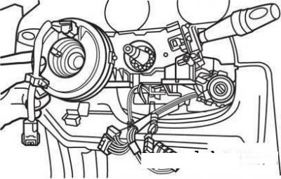
Removing the contact disk from the steering shaft
Remove the contact disk.
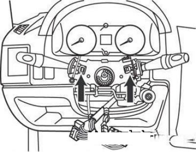
Steering column switch block mounting latches
Disconnect the connectors and remove the steering column switch assembly by pressing the latches down.
Installation is carried out in the reverse order of removal.