
2. Press the spring retaining ring and remove the switch.
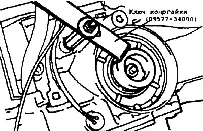
3. Insert the special tool into the cutout in the plunger to prevent it from turning and use the adapter to fix the plunger in place.
Warning:
- 1. Do not press on the plunger with a special tool.
- 2. Attach the adapter to the low-speed/reverse brake receptacle by hand only and do not tighten it excessively.
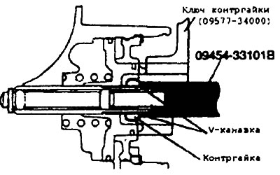
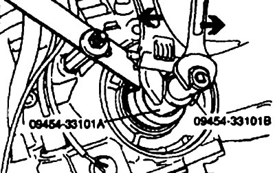
4. Loosen the lock nut just before the V-groove in the adjusting rod (see fig.) and tighten the special tool (09454-33101 B) until it contacts the lock nut.
 |
 |
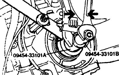
5. Place the special tool (09454-33101 A) on the lock nut. Turn the servo socket wrench counterclockwise and turn the inner cylinder clockwise to lock the lock nut and the servo socket wrench B (09454-33101 B) as the special tool.
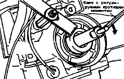
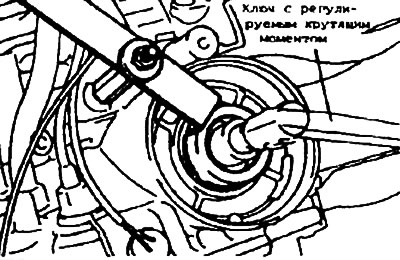
6. Place the adjustable torque wrench on the special tool (09454-33101 B) and repeat the tightening-loosening cycle twice with a tightening torque of 10 Nm. Then loosen the special tool (09454-33101 B) by 2-21/4 turns.
 |
 |
7. Place the special tool (09454-33101 A) on the lock nut. Turn the servo drive socket wrench A clockwise and the inner wrench counterclockwise to release the lock nut from the action of the special tool (09454-33101 B).
Warning: Try to apply equal torque to the two special tools when loosening the lock nut.
8. Tighten the lock nut by hand until it reaches the plunger. Then tighten it to the specified torque using a torque wrench.
- Lock nut: 29 Nm
Warning: Using a socket wrench or torque wrench could cause the lock nut to turn along with the adjusting rod.
9. Remove the special tool to secure the plunger and plug to the standard on the low speed/reverse brake pressure inlet.